
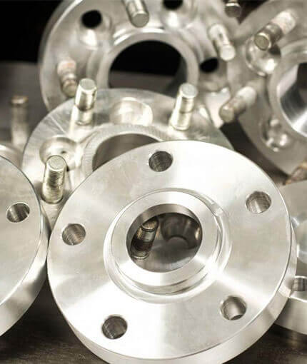
The Stainless Steel Flanges are available in various shapes, sizes and pressure ratings. The flanges are manufactured using optimum quality material and thereby ensure excellent durability and corrosion resistance. Ideal for high temperature and pressure applications, these flanges are customized as per the precise demands of the clients. These flanges are highly praised for offering hassle free performance and high functionality.
We manufacture a wide range of variety of flanges including Slip on, Weld Neck, Blind, Threaded, Lap Joint Stainless Steel Plate Flanges, Stainless Steel Back up Flanges, etc.
Flanges are piping components bolted together using gasket in between two flanges as a sealing material. Flanges are used to connect pipes with each other, connect pipes to flanged valves, connect pipes to flanged fittings, connect pipes to flanged piping specialty items such as strainers and to isolate piping sections using a blind flange.
Threaded
Socket Welding
(½” to 2½” Only)
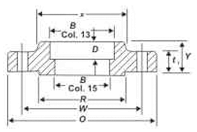
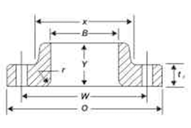
Slip-on Welding
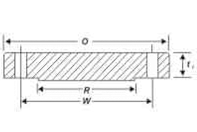
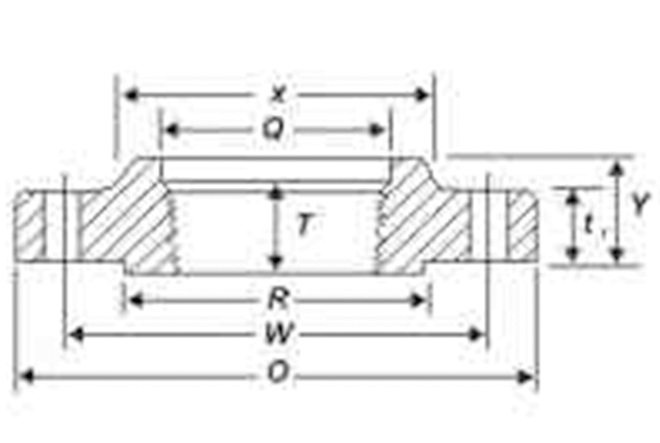
Blind
Lapped
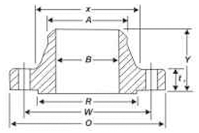
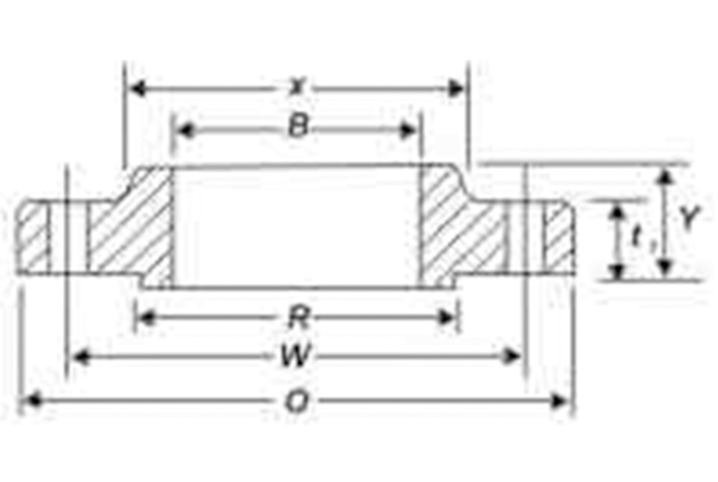
Welding Neck
Dimensions of Flanges as Per Ansi B 16.5
Dimensions of Class 150 Flanges as Per Ansi B 16.5
| 1 | 2 | 3 | 4 | 5 | 6 | 7 | 8 | 9 | 10 | 11 | 12 | 13 | 14 | 15 | 16 | 17 | 18 | 19 |
|---|---|---|---|---|---|---|---|---|---|---|---|---|---|---|---|---|---|---|
|
Nominal Pipe Size NPS |
Outside Diameter of Flange O |
Thickness of Flange, Min., t1 |
Drilling |
Diameter of Hub, X |
Hub Diameter Begin- ning of Chamfer Welding Neck A |
Lenght Thru Hub |
Threaded/ Lenght Threaded Min. B |
Bore |
Comer Radius of Bore Lapped Flange and Pipe, R |
Depth of Socket D |
Diameter of RF, R |
|||||||
|
Thickness Lap Joint Min., t1 |
Diameter of Blot Circle W |
Diameter of Blot Holes |
Numbers of Blots |
Threaded /Slip-On /Socket Welding, Y |
Lapped Y |
Welding, Y |
Slip-On/ Socket Welding. Min. B |
Lapped Min. B |
Welding Neck/ Socket Welding B (Note(2) |
|||||||||
| 1/2 | 90 | 9.6 | 11.2 | 60.3 | 15.9 | 4 | 30 | 21.3 | 14 | 16 | 46 | 16 | 22.2 | 22.9 | 15.8 | 3 | 10 | 34.9 |
| 3/4 | 100 | 11.2 | 12.7 | 6.9.9 | 15.9 | 4 | 38 | 26.7 | 14 | 16 | 51 | 16 | 27.7 | 28.2 | 20.9 | 3 | 11 | 42.9 |
| 1 | 110 | 12.7 | 14.3 | 79.4 | 15.9 | 4 | 49 | 33.4 | 16 | 17 | 54 | 17 | 34.5 | 34.9 | 26.6 | 3 | 13 | 50.8 |
| 11/4 | 115 | 14.3 | 15.9 | 88.9 | 15.9 | 4 | 59 | 42.2 | 19 | 21 | 56 | 21 | 43.2 | 43.7 | 35.1 | 5 | 14 | 63.5 |
| 11/2 | 125 | 15.9 | 17.5 | 984 | 15.9 | 4 | 65 | 48.3 | 21 | 22 | 60 | 22 | 49.5 | 50.0 | 40.9 | 6 | 16 | 73.0 |
| 2 | 150 | 17.5 | 19.1 | 120.7 | 19.1 | 4 | 78 | 6.0.3 | 24 | 25 | 62 | 25 | 61.9 | 62.5 | 52.5 | 8 | 17 | 92.1 |
| 2 1/2 | 180 | 20.7 | 22.3 | 139.7 | 19.1 | 4 | 90 | 73.0 | 27 | 29 | 68 | 29 | 74.6 | 75.4 | 62.7 | 8 | 19 | 104.8 |
| 3 | 190 | 22.3 | 23.9 | 152.4 | 19.1 | 4 | 108 | 88.9 | 29 | 30 | 68 | 30 | 90.7 | 91.4 | 77.9 | 10 | 21 | 127.0 |
| 31/2 | 215 | 22.3 | 23.9 | 177.8 | 19.1 | 8 | 122 | 101.6 | 30 | 32 | 70 | 32 | 103.4 | 104.1 | 90.1 | 10 | - | 139.7 |
| 4 | 230 | 22.3 | 23.9 | 190.5 | 19.1 | 8 | 135 | 114.3 | 32 | 33 | 75 | 33 | 116.1 | 116.8 | 102.9 | 11 | - | 157.2 |
| 5 | 255 | 22.3 | 23.9 | 215.9 | 22.3 | 8 | 164 | 141.3 | 35 | 36 | 87 | 36 | 143.8 | 144.4 | 128.2 | 11 | - | 185.7 |
| 6 | 280 | 23.9 | 25.4 | 241.3 | 22.3 | 8 | 192 | 168.3 | 38 | 40 | 87 | 40 | 170.7 | 171.4 | 154.1 | 13 | - | 215.9 |
| 8 | 345 | 27.0 | 28.6 | 298.2 | 22.3 | 8 | 246 | 219.1 | 43 | 44 | 100 | 44 | 221.5 | 222.2 | 202.7 | 13 | - | 269.9 |
| 10 | 4.5 | 28.6 | 30.2 | 362.0 | 25.4 | 12 | 3.5 | 273.0 | 48 | 49 | 100 | 49 | 276.2 | 277.4 | 254.6 | 13 | - | 323.8 |
| 12 | 845 | 3.2 | 31.8 | 431.8 | 25.4 | 12 | 365 | 323.8 | 54 | 55 | 113 | 55 | 327.0 | 328.2 | 304.8 | 13 | - | 381.0 |
| 14 | 535 | 33.4 | 35.0 | 476.3 | 28.6 | 12 | 400 | 355.6 | 56 | 79 | 125 | 57 | 359.2 | 360.2 | To be Specified by Purchaser | 13 | - | 412.8 |
| 16 | 595 | 35.0 | 36.6 | 539.8 | 28.6 | 16 | 457 | 406.4 | 62 | 87 | 125 | 64 | 410.5 | 411.2 | 13 | - | 469.9 | |
| 18 | 635 | 38.1 | 39.7 | 577.9 | 31.8 | 16 | 505 | 457.0 | 67 | 97 | 138 | 68 | 461.8 | 462.3 | 13 | - | 533.4 | |
| 20 | 700 | 41.3 | 42.9 | 635.0 | 31.8 | 20 | 559 | 508.0 | 71 | 103 | 143 | 73 | 513.1 | 514.4 | 13 | - | 584.2 | |
| 24 | 815 | 46.1 | 47.7 | 749.3 | 35.0 | 20 | 663 | 610.0 | 81 | 111 | 151 | 83 | 616.0 | 616.0 | 13 | - | 692.2 | |
Dimensions of Class 300 Flanges as Per Ansi B 16.5
| 1 | 2 | 3 | 4 | 5 | 6 | 7 | 8 | 9 | 10 | 11 | 12 | 13 | 14 | 15 | 16 | 17 | 18 | 19 | 20 |
|---|---|---|---|---|---|---|---|---|---|---|---|---|---|---|---|---|---|---|---|
|
Nominal Pipe Size NPS |
Outside Diameter of Flange O |
Thickness of Flange, Min., t1 |
Drilling |
Diameter of Hub, X |
Hub Diameter Begin- ning of Chamfer Welding Neck A |
Lenght Thru Hub |
Threaded/ Lenght Threaded Min. B |
Bore |
Comer Radius of Bore Lapped Flange and Pipe, R |
Counter Bore Threaded FLANGE Min Q |
Depth of Socket D |
Diameter of RF, R |
|||||||
|
Thickness Lap Joint Min., t1 |
Diameter of Blot Circle W |
Diameter of Blot Holes |
Numbers of Blots |
Threaded /Slip-On /Socket Welding, Y |
Lapped Y |
Welding, Y |
Slip-On/ Socket Welding. Min. B |
Lapped Min. B |
Welding Neck/ Socket Welding B (Note(2) |
||||||||||
| 1/2 | 95 | 12.7 | 14.3 | 66.7 | 15.9 | 4 | 38 | 21.3 | 21 | 22 | 51 | 16 | 22.2 | 22.9 | 15.8 | 3 | 23.6 | 10 | 34.9 |
| 3/4 | 115 | 14.9 | 15.9 | 82.6 | 19.1 | 4 | 48 | 26.7 | 24 | 25 | 56 | 16 | 27.7 | 28.2 | 20.9 | 3 | 29.0 | 11 | 42.9 |
| 1 | 125 | 15.9 | 17.5 | 88.9 | 19.1 | 4 | 54 | 33.4 | 25 | 27 | 60 | 18 | 34.5 | 34.9 | 26.6 | 3 | 35.8 | 13 | 50.8 |
| 11/4 | 135 | 17.5 | 19.1 | 98.4 | 19.1 | 4 | 64 | 42.2 | 25 | 27 | 64 | 21 | 43.2 | 43.7 | 35.1 | 5 | 44.4 | 14 | 63.5 |
| 11/2 | 155 | 19.1 | 20.7 | 114.3 | 22.2 | 4 | 70 | 48.3 | 29 | 30 | 67 | 23 | 49.5 | 50.2 | 40.9 | 6 | 50.3 | 16 | 73.0 |
| 2 | 165 | 207 | 22.3 | 127.0 | 19.0 | 4 | 84 | 60.3 | 32 | 33 | 68 | 29 | 61.9 | 62.5 | 52.5 | 8 | 63.5 | 17 | 92.1 |
| 2 1/2 | 190 | 23.9 | 25.4 | 149.2 | 22.3 | 4 | 100 | 73.0 | 37 | 38 | 75 | 32 | 74.6 | 754 | 62.7 | 8 | 76.2 | 19 | 104.8 |
| 3 | 210 | 27.0 | 28.6 | 168.3 | 22.3 | 4 | 117 | 88.9 | 41 | 43 | 78 | 32 | 90.7 | 91.4 | 77.9 | 10 | 92.2 | 21 | 127.0 |
| 31/2 | 230 | 28.6 | 30.2 | 184.2 | 22.3 | 8 | 133 | 101.6 | 43 | 44 | 79 | 37 | 103.4 | 104.1 | 90.1 | 10 | 104.9 | - | 139.7 |
| 4 | 255 | 30.2 | 31.8 | 200.0 | 22.3 | 8 | 146 | 114.3 | 46 | 48 | 84 | 37 | 116.1 | 116.1 | 102.3 | 11 | 117.6 | - | 157.2 |
| 5 | 280 | 33.4 | 35.0 | 235.0 | 22.3 | 8 | 178 | 141.3 | 49 | 51 | 97 | 43 | 143.8 | 144.4 | 128.2 | 11 | 144.4 | - | 185.7 |
| 6 | 320 | 35.0 | 36.6 | 269.9 | 22.3 | 8 | 206 | 168.3 | 51 | 52 | 97 | 47 | 170.7 | 171.4 | 154.1 | 13 | 171.1 | - | 215.9 |
| 8 | 380 | 39.7 | 41.3 | 330.2 | 25.4 | 8 | 260 | 219.1 | 60 | 62 | 110 | 51 | 221.5 | 222.2 | 202.7 | 13 | 222.2 | - | 269.9 |
| 10 | 445 | 46.1 | 47.7 | 387.4 | 28.6 | 12 | 321 | 273.0 | 65 | 95 | 116 | 56 | 276.2 | 277.4 | 254.6 | 13 | 276.2 | - | 323.8 |
| 12 | 520 | 49.3 | 50.8 | 450.8 | 31.8 | 12 | 375 | 323.8 | 71 | 102 | 129 | 61 | 327.0 | 328.2 | 304.8 | 13 | 328.3 | - | 381.0 |
| 14 | 585 | 52.4 | 54.0 | 514.4 | 31.8 | 12 | 425 | 355.6 | 75 | 111 | 141 | 64 | 359.2 | 360.2 | To be Specified by Purchaser | 13 | 360.4 | - | 412.8 |
| 16 | 650 | 55.6 | 57.2 | 571.5 | 35.0 | 16 | 483 | 406.4 | 81 | 121 | 144 | 69 | 410.5 | 411.2 | 13 | 411.2 | - | 469.9 | |
| 18 | 710 | 58.8 | 60.4 | 628.6 | 35.0 | 16 | 533 | 457.0 | 87 | 130 | 157 | 70 | 461.8 | 462.3 | 13 | 462.0 | - | 533.4 | |
| 20 | 775 | 60.0 | 63.5 | 685.8 | 35.0 | 20 | 587 | 508.0 | 94 | 140 | 160 | 74 | 513.1 | 514.4 | 13 | 512 | - | 584.2 | |
| 24 | 915 | 68.3 | 69.9 | 812.8 | 41.3 | 20 | 702 | 610.0 | 150 | 152 | 167 | 83 | 616.0 | 616.0 | 13 | 614.4 | - | 692.2 | |
Note:
- 1. Height of RE 2mm
- 2. Dimensions column 16 Correspond to the inside diameters of pipe as given in ASME B36.10M for Standard Wall Pipe, 04 Thickness of Standard Wall is the same as Schedule 40 in Size NPS 10 and smaller. These bore size are furnished unless Otherwise specified by the Purchaser.
Dimensions of Class 600 Flanges as Per Ansi B 16.5
| 1 | 2 | 3 | 4 | 5 | 6 | 7 | 8 | 9 | 10 | 11 | 12 | 13 | 14 | 15 | 16 | 17 | 18 | 19 |
|---|---|---|---|---|---|---|---|---|---|---|---|---|---|---|---|---|---|---|
| Nominal Pipe Size NPS |
Outside Diameter of Flange O |
Thickness of Flanges Min f |
Diameter of Hub, X |
Drilling |
Hub Diameter Begin- ning of Chamfer Welding Neck A |
Length Thru Hub |
Threaded / Length Threaded Flange Min., T |
Bore |
Corner Radius of Bore of Lapped Flange and Pipe, r |
Counter- Bore Threaded Flange Min., Q |
Diameter of RF R |
Socket Weld D | ||||||
|
Diameter of Bolt Circle W |
Diameter of Bolt Holes in |
Number of Bolts |
Threaded/ Slip-On Y |
Lapped, Y | Welding Neck Y |
Slip-On Min., B |
Lapped Min., B |
Welding Neck B | ||||||||||
| 1/2 | 95 | 14.3 | 38 | 66.7 | 15.9 | 4 | 21.3 | 22 | 22 | 52 | 16 | 22.2 | 22.9 | 3 | 23.6 | 10 | 34.9 | |
| 3/4 | 115 | 15.9 | 48 | 82.6 | 19.1 | 4 | 26.7 | 25 | 25 | 57 | 16 | 27.7 | 28.2 | 3 | 29.6 | 11 | 42.9 | |
| 1 | 125 | 17.5 | 54 | 88.9 | 19.1 | 4 | 33.4 | 27 | 27 | 62 | 18 | 34.5 | 34.9 | 3 | 35.8 | 13 | 50.8 | |
| 1 1/4 | 135 | 20.7 | 64 | 98.4 | 19.1 | 4 | 42.2 | 29 | 29 | 67 | 21 | 43.2 | 43.7 | 5 | 44.4 | 14 | 63.5 | |
| 11/2 | 155 | 22.3 | 70 | 114.3 | 22.3 | 4 | 48.3 | 32 | 32 | 70 | 23 | 49.5 | 50.0 | 6 | 50.6 | 16 | 73.0 | |
| 2 | 165 | 25.4 | 84 | 127.0 | 19.1 | 8 | 60.3 | 37 | 37 | 73 | 29 | 61.9 | 62.5 | To be Specified by Purchaser | 8 | 63.5 | 17 | 92.7 |
| 21/2 | 190 | 28.6 | 100 | 149.2 | 22.3 | 8 | 73.0 | 41 | 41 | 79 | 32 | 74.6 | 75.4 | 8 | 76.2 | 19 | 104.8 | |
| 3 | 210 | 31.8 | 117 | 168.3 | 22.3 | 8 | 88.9 | 46 | 46 | 83 | 35 | 90.7 | 91.4 | 10 | 92.2 | 21 | 127.0 | |
| 4 | 230 | 35.0 | 133 | 184.2 | 25.4 | 8 | 101.6 | 49 | 49 | 86 | 40 | 103.4 | 104.1 | 10 | 104.9 | - | 139.7 | |
| 5 | 330 | 44.5 | 189 | 266.7 | 28.6 | 8 | 141.36 | 60 | 60 | 114 | 48 | 143.8 | 144.4 | 22 | 144.4 | - | 185.7 | |
| 6 | 355 | 47.7 | 222 | 292.1 | 28.6 | 12 | 168.3 | 67 | 67 | 117 | 51 | 170.7 | 171.4 | 13 | 171.4 | - | 215.9 | |
| 8 | 420 | 55.6 | 273 | 349.2 | 31.8 | 12 | 219.1 | 76 | 76 | 133 | 58 | 221.5 | 222.2 | 13 | 222.2 | - | 269.9 | |
| 10 | 510 | 63.5 | 343 | 431.8 | 35.0 | 16 | 273.0 | 86 | 111 | 152 | 66 | 276.2 | 277.4 | 13 | 276.2 | - | 323.8 | |
| 12 | 560 | 66.7 | 400 | 489.0 | 35.0 | 20 | 323.8 | 92 | 117 | 156 | 70 | 327.0 | 328.2 | 13 | 328.6 | - | 381.0 | |
| 14 | 605 | 69.9 | 432 | 527.0 | 38.1 | 20 | 355.6 | 94 | 94 | 165 | 74 | 359.2 | 360.2 | 13 | 360.4 | - | 412.8 | |
| 16 | 605 | 76.2 | 495 | 603.0 | 41.3 | 20 | 406.4 | 106 | 140 | 178 | 48 | 410.5 | 411.2 | 13 | 411.2 | - | 469.9 | |
| 18 | 745 | 82.6 | 546 | 654.0 | 44.5 | 20 | 457.0 | 117 | 152 | 184 | 80 | 461.8 | 162.3 | 13 | 462.0 | - | 533.4 | |
| 20 | 815 | 88.9 | 610 | 723.9 | 44.5 | 24 | 508.0 | 127 | 165 | 190 | 83 | 513.1 | 514.4 | 13 | 512.8 | - | 584.2 | |
| 24 | 940 | 101.6 | 718 | 838.2 | 50.8 | 24 | 610.0 | 140 | 184 | 203 | 93 | 616.0 | 616.0 | 13 | 614.4 | - | 692.2 | |
Note:
- 1. Height of 7mm
Dimensions of Class 1500 Flanges as Per Ansi B 16.5
| 1 | 2 | 3 | 4 | 5 | 6 | 7 | 8 | 9 | 10 | 11 | 12 | 13 | 14 | 15 | 16 | 17 | 18 | 19 |
|---|---|---|---|---|---|---|---|---|---|---|---|---|---|---|---|---|---|---|
| Nominal Pipe Size NPS |
Outside Diameter of Flange O |
Thickness of Flanges Min f |
Diameter of Hub, X |
Drilling |
Hub Diameter Begin- ning of Chamfer Welding Neck A |
Length Thru Hub |
Threaded / Length Threaded Flange Min., T |
Bore |
Corner Radius of Bore of Lapped Flange and Pipe, r |
Counter- Bore Threaded Flange Min., Q |
Diameter of RF R |
Socket Weld D | ||||||
|
Diameter of Bolt Circle W |
Diameter of Bolt Holes in |
Number of Bolts |
Threaded/ Slip-On Y |
Lapped, Y | Welding Neck Y |
Slip-On Min., B |
Lapped Min., B |
Welding Neck B | ||||||||||
| 1/2 | 121 | 22.3 | 38 | 82.6 | 22.3 | 4 | 21.3 | 32 | 32 | 60 | 23 | 22.2 | 22.9 | 3 | 23.6 | 10 | 34.9 | |
| 3/4 | 130 | 25.4 | 44 | 88.9 | 22.3 | 4 | 26.7 | 35 | 35 | 70 | 26 | 27.7 | 28.2 | 3 | 29.0 | 11 | 42.9 | |
| 1 | 149 | 28.6 | 52 | 101.6 | 25.4 | 4 | 33.4 | 41 | 41 | 73 | 29 | 34.5 | 34.9 | 3 | 35.8 | 13 | 50.8 | |
| 1 1/4 | 159 | 28.6 | 64 | 111.1 | 254 | 4 | 42.2 | 41 | 41 | 73 | 31 | 43.2 | 43.7 | 5 | 44.4 | 14 | 63.5 | |
| 11/2 | 178 | 31.8 | 70 | 123.8 | 28.6 | 4 | 48.3 | 44 | 44 | 83 | 32 | 49.5 | 50.0 | 6 | 50.6 | 16 | 73.0 | |
| 2 | 216 | 38.1 | 105 | 165.1 | 25.4 | 8 | 60.3 | 57 | 57 | 102 | 39 | 61.9 | 62.5 | To be Specified by Purchaser | 8 | 63.5 | 17 | 92.1 |
| 21/2 | 244 | 41.3 | 124 | 190.5 | 28.6 | 8 | 73.0 | 64 | 64 | 105 | 48 | 74.6 | 75.4 | 8 | 76.2 | 19 | 104.8 | |
| 3 | 267 | 47.7 | 133 | 203.2 | 31.8 | 8 | 88.9 | - | 73 | 117 | - | - | 91.4 | 10 | - | - | 127.0 | |
| 4 | 311 | 54.0 | 162 | 241.3 | 35.0 | 8 | 114.3 | - | 90 | 124 | - | - | 116.8 | 11 | - | - | 139.7 | |
| 5 | 375 | 73.1 | 197 | 292.1 | 41.3 | 8 | 141.36 | - | 105 | 156 | - | - | 144.4 | 11 | - | - | 157.2 | |
| 6 | 394 | 82.6 | 229 | 317.5 | 38.1 | 12 | 168.3 | - | 119 | 171 | - | - | 171.4 | 13 | - | - | 215.9 | |
| 8 | 483 | 92.1 | 292 | 393.7 | 44.5 | 12 | 219.1 | - | 143 | 213 | - | - | 222.2 | 13 | - | - | 269.9 | |
| 10 | 584 | 108.0 | 368 | 482.6 | 50.8 | 12 | 273.0 | - | 178 | 254 | - | - | 277.4 | 13 | - | - | 323.8 | |
| 12 | 673 | 123.9 | 451 | 571.5 | 54.0 | 16 | 323.8 | - | 219 | 283 | - | - | 328.2 | 13 | - | - | 381.0 | |
| 14 | 749 | 133.4 | 495 | 635.0 | 60.7 | 16 | 355.6 | - | 241 | 298 | - | - | 360.2 | 13 | - | - | 412.8 | |
| 16 | 826 | 146.1 | 552 | 704.8 | 66.7 | 16 | 406.4 | - | 260 | 311 | - | - | 411.2 | 13 | - | - | 469.9 | |
| 18 | 914 | 162.0 | 597 | 774.7 | 73.0 | 16 | 457.0 | - | 276 | 327 | - | - | 462.3 | 13 | - | - | 533.4 | |
| 20 | 984 | 177.8 | 641 | 831.8 | 79.4 | 16 | 508.0 | - | 292 | 356 | - | - | 514.4 | 13 | - | - | 584.2 | |
| 24 | 1168 | 203.2 | 762 | 990.6 | 92.1 | 16 | 610.0 | - | 330 | 408 | - | - | 616.0 | 13 | - | - | 692.2 | |
Note:
- 1. Height of 7mm
Dimensions of Flanges as Per Table BS-10
For Working Steam Pressure Upto 50 lbs Per sq. Inch
| Nominal Pipe Size-1 | O.D. of Pipe | O.D. | P.C.D. | No. of Bolt | Dia of Bolt | Thickness |
|---|---|---|---|---|---|---|
| 1/2" | 21.3 | 95.3 | 66.7 | 4 | 12.7 | 4.8 |
| 3/4" | 26.7 | 101.6 | 73.0 | 4 | 12.7 | 4.8 |
| 1" | 33.4 | 114.3 | 82.6 | 4 | 12.7 | 4.8 |
| 11/4" | 42.2 | 120.7 | 87.3 | 4 | 12.7 | 6.4 |
| 11/2" | 48.3 | 133.4 | 98.4 | 4 | 12.7 | 6.4 |
| 2" | 60.3 | 152.4 | 114.3 | 4 | 15.9 | 7.9 |
| 21/2" | 73.0 | 165.1 | 127.0 | 4 | 15.9 | 7.9 |
| 3" | 88.9 | 184.2 | 146.1 | 4 | 15.9 | 9.5 |
| 31/2" | 101.6 | 203.2 | 165.1 | 4 | 15.9 | 9.5 |
| 4" | 114.3 | 215.9 | 177.8 | 4 | 15.9 | 9.5 |
| 5" | 141.3 | 254.0 | 209.6 | 8 | 15.9 | 12.7 |
| 6" | 168.3 | 279.4 | 228.6 | 8 | 15.9 | 12.7 |
| 7" | 190.5 | 304.8 | 260.4 | 8 | 15.9 | 12.7 |
| 8" | 219.1 | 336.6 | 292.1 | 8 | 15.9 | 12.7 |
| 9" | 244.5 | 368.3 | 323.9 | 8 | 15.9 | 15.9 |
| 10" | 273.0 | 406.4 | 355.6 | 8 | 19.1 | 15.9 |
| 12" | 323.9 | 457.2 | 406.4 | 12 | 19.1 | 15.9 |
| 14" | 355.6 | 527.1 | 469.9 | 12 | 22.2 | 19.1 |
| 16" | 406.4 | 577.9 | 520.7 | 12 | 22.2 | 19.1 |
| 18" | 457.2 | 641.4 | 584.2 | 12 | 22.2 | 22.2 |
| 20" | 508.0 | 704.9 | 641.4 | 16 | 22.5 | 25.4 |
| 24" | 609.6 | 825.5 | 755.7 | 16 | 25.4 | 28.6 |
For Working Steam Pressure From 50 lbs to 100 lbs Per sq. Inch
| Nominal Pipe Size-2 | O.D. of Pipe | O.D. | P.C.D. | No. of Bolt | Dia of Bolt | Thickness |
|---|---|---|---|---|---|---|
| 1/2" | 21.3 | 95.3 | 66.3 | 4 | 12.7 | 6.4 |
| 3/4" | 26.7 | 101.6 | 73.0 | 4 | 12.7 | 6.4 |
| 1" | 33.4 | 114.3 | 82.6 | 4 | 12.7 | 7.1 |
| 11/4" | 42.2 | 120.7 | 87.3 | 4 | 12.7 | 7.9 |
| 11/2" | 48.3 | 133.4 | 98.4 | 4 | 12.7 | 8.7 |
| 2" | 60.3 | 152.4 | 114.3 | 4 | 15.9 | 9.5 |
| 21/2" | 73.0 | 165.1 | 127.0 | 4 | 15.9 | 10.3 |
| 3" | 88.9 | 184.2 | 146.1 | 4 | 15.9 | 11.1 |
| 31/2" | 101.6 | 203.2 | 165.1 | 8 | 15.9 | 11.9 |
| 4" | 114.3 | 215.9 | 177.8 | 8 | 15.9 | 12.7 |
| 5" | 141.3 | 254.0 | 209.6 | 8 | 15.9 | 14.3 |
| 6" | 168.3 | 279.4 | 228.6 | 8 | 19.1 | 17.5 |
| 7" | 190.5 | 304.8 | 260.4 | 8 | 19.1 | 19.6 |
| 8" | 219.1 | 336.6 | 292.1 | 8 | 19.1 | 19.6 |
| 9" | 244.5 | 368.3 | 323.9 | 12 | 19.1 | 20.6 |
| 10" | 273.0 | 406.4 | 355.6 | 12 | 19.1 | 22.2 |
| 12" | 323.9 | 257.2 | 406.4 | 12 | 22.2 | 25.4 |
| 14" | 355.6 | 527.1 | 469.9 | 12 | 22.2 | 25.4 |
| 16" | 406.4 | 577.9 | 520.7 | 12 | 22.2 | 25.4 |
| 18" | 457.2 | 641.4 | 584.2 | 16 | 22.2 | 28.6 |
| 20" | 508.0 | 704.9 | 647.4 | 16 | 22.2 | 31.8 |
| 24" | 609.6 | 825.5 | 755.7 | 16 | 25.4 | 38.1 |
For Working Steam Pressure From 100 lbs to 150 lbs Per sq. Inch
| Nominal Pipe Size-3 | O.D. of Pipe | O.D. | P.C.D. | No. of Bolt | Dia of Bolt | Thickness |
|---|---|---|---|---|---|---|
| 1/2" | 21.3 | 95.3 | 66.7 | 4 | 12.7 | 9.5 |
| 3/4" | 26.7 | 101.6 | 73.0 | 4 | 12.7 | 9.5 |
| 1" | 33.4 | 120.7 | 87.3 | 4 | 15.9 | 9.5 |
| 11/4" | 42.2 | 133.4 | 98.4 | 4 | 15.9 | 12.7 |
| 11/2" | 48.3 | 139.7 | 104.8 | 4 | 15.9 | 12.7 |
| 2" | 60.3 | 165.1 | 127.0 | 4 | 15.9 | 15.9 |
| 21/2" | 73.0 | 184.2 | 146.1 | 8 | 15.9 | 15.9 |
| 3" | 88.9 | 203.2 | 165.1 | 8 | 15.9 | 15.9 |
| 31/2" | 101.6 | 215.9 | 177.8 | 8 | 15.9 | 19.1 |
| 4" | 114.3 | 228.6 | 190.5 | 8 | 19.1 | 19.1 |
| 5" | 141.3 | 279.4 | 235.0 | 8 | 19.1 | 22.2 |
| 6" | 168.3 | 304.8 | 260.4 | 12 | 19.1 | 22.2 |
| 7" | 190.5 | 336.6 | 292.1 | 12 | 19.1 | 22.2 |
| 8" | 219.1 | 368.3 | 323.9 | 12 | 19.1 | 25.4 |
| 9" | 244.5 | 406.4 | 355.6 | 12 | 22.2 | 25.4 |
| 10" | 273.0 | 431.8 | 381.0 | 12 | 22.2 | 25.4 |
| 12" | 323.9 | 489.0 | 438.2 | 16 | 22.2 | 28.6 |
| 14" | 355.6 | 525.5 | 495.3 | 16 | 25.4 | 31.8 |
| 16" | 406.4 | 609.6 | 552.5 | 20 | 25.4 | 31.8 |
| 18" | 457.2 | 673.1 | 609.6 | 20 | 28.6 | 34.9 |
| 20" | 508.0 | 736.6 | 673.1 | 24 | 28.6 | 38.1 |
| 24" | 609.6 | 850.9 | 781.1 | 24 | 31.8 | 41.3 |
For Working Steam Pressure From 150 lbs to 250 lbs Per sq. Inch
| Nominal Pipe Size-4 | O.D. of Pipe | O.D. | P.C.D. | No. of Bolt | Dia of Bolt | Thickness |
|---|---|---|---|---|---|---|
| 1/2" | 21.3 | 114.3 | 82.6 | 4 | 15.9 | 12.7 |
| 3/4" | 26.7 | 114.3 | 82.6 | 4 | 15.9 | 12.7 |
| 1" | 33.4 | 120.7 | 87.3 | 4 | 15.9 | 14.3 |
| 11/4" | 42.2 | 133.4 | 98.4 | 4 | 15.9 | 17.5 |
| 11/2" | 48.3 | 139.7 | 104.8 | 4 | 15.9 | 17.5 |
| 2" | 60.3 | 165.1 | 127.0 | 4 | 15.9 | 19.1 |
| 21/2" | 73.0 | 184.2 | 146.1 | 8 | 15.9 | 19.1 |
| 3" | 88.9 | 203.2 | 165.1 | 8 | 15.9 | 22.2 |
| 31/2" | 101.6 | 215.9 | 177.8 | 8 | 15.9 | 22.2 |
| 4" | 114.3 | 228.6 | 190.5 | 8 | 15.9 | 25.4 |
| 5" | 141.3 | 279.4 | 235.0 | 8 | 19.1 | 28.6 |
| 6" | 168.3 | 302.8 | 260.4 | 12 | 19.1 | 28.6 |
| 7" | 190.5 | 336.6 | 292.1 | 12 | 19.1 | 31.8 |
| 8" | 219.1 | 368.3 | 323.9 | 12 | 19.1 | 31.8 |
| 9" | 244.5 | 406.4 | 355.6 | 12 | 22.2 | 34.9 |
| 10" | 273.0 | 431.8 | 381.0 | 12 | 22.2 | 34.9 |
| 12" | 323.9 | 489.0 | 438.2 | 16 | 22.2 | 38.1 |
| 14" | 355.6 | 552.5 | 495.3 | 16 | 25.4 | 41.3 |
| 16" | 406.4 | 609.6 | 552.5 | 20 | 25.4 | 44.5 |
| 18" | 457.2 | 673.1 | 609.6 | 20 | 28.6 | 47.6 |
| 20" | 508.0 | 736.6 | 673.1 | 24 | 28.6 | 50.8 |
| 24" | 609.6 | 850.9 | 781.1 | 24 | 31.8 | 57.2 |
Note:
- 1. For 12.7mm and 15.87mm Bolts Dia the Diameters of the Holes Will be 1.58mm Larger and for 19.01 and Above the Hole Dia Will be 3.17 Larger